|
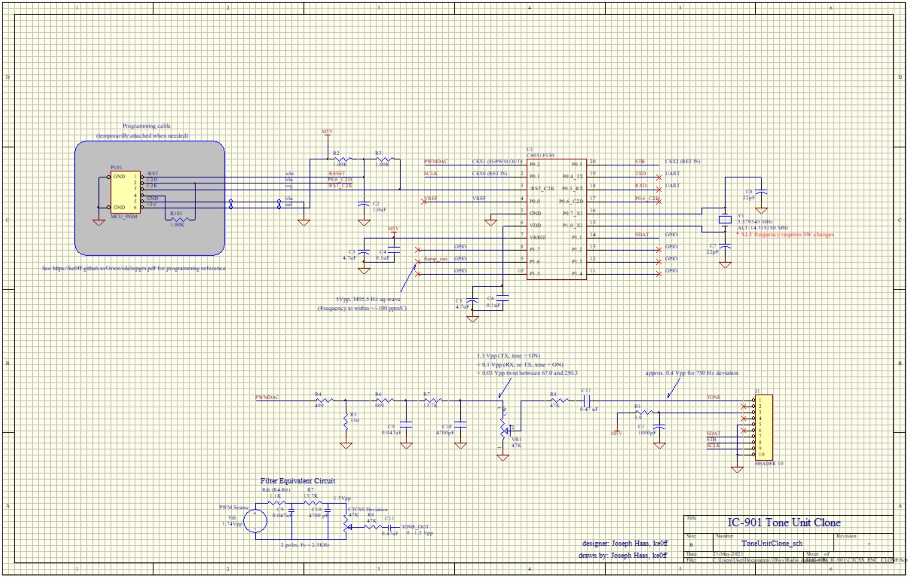
The software operates completely using interrupts. The main loop is empty except for an instruction to place the MCU into a "wait-for-interrupt" state.
There is one timer interrupt, and one Programmable Counter/timer Array (PCA) interrupt. The timer interrupt (Timer 1) handles the code to process the DDS tone generator.
The PCA captures SCLK and STB edges and parses them into an 8-bit result which contains bit-mapped information on tone frequency and tone on/off status.
Timer 1 implements a simple, 1-tone DDS generator that is phase-accumulator based (see NXP's AN1771 for a detailed treatise
on the subject). For the DAC, one of the PCA PWMs is used, but not as an interrupt. The idea is that since timer 1 and the PCA run off of the same clock base, they will remain synchronized.
This allows the DDS algorithm running in Timer 1 to write updates to the PWM without worrying about pop-noise that can occur if the update isn’t precisely aligned to the DDS sample clock.
The PCA interrupt is the most complicated ISR in this project. It captures serial clock and strobe edges along with the data signal and then parses them into 1’s or 0’s which are shifted
into the result register. The strobe edge detect parses the data received and updates the tone frequency or turns off the tone based on the bit pattern in the data register.
This part of the code essentially emulates a CD4094 shift register IC which is what is used on the original Tone Unit to capture the data message.
The main application initializes the GPIO and peripherals, and then enters the main process loop (MPL) which, as noted, is simply a write to an MCU register to place the MCU into an
"idle" state until an interrupt occurs.
Measurements using a toggle function at an un-used I/O pin indicate that the ISRs occupy approximately 1/5 of the available processor time. Running at the colorburst * 4 frequency would give
more headroom, but this isn't likely needed for the purposes of gaining more processor cycles.
I did not manage to conjur a bug-free application on the first pass. I ended up with a couple of bugs that were minor, but one took a bit of hair-pulling to locate. The first bug found was
in the shift code. I shifted the data in the wrong direction (D'OH!!!). The second bug was a cut-n-paste error and was the hardest to find. The pasted line was edited except for the type cast, which
left it with the wrong data size for an extern reference. No error or warning resulted, but the code didn't work right. Close, but no cigar. Overall, it came together rather well and does
what it needs to do.
DPL is an option I'm considering. I need to review the specs for the data sequencing. The main problem lies in how to configure the DPL tone selection. The IC-901 only sends 38 unique
codes to the Tone Unit. These currently align with particular CTCSS frequencies. The 901 just doesn't have any provisions for any other codes. The solution would be to re-assign some of the
CTCSS codes to DPL. The idea would be to choose codes that correspond to CTCSS frequencies that are rare, or at least, rare for one's area. For me, I'd choose the top 5 or 6 codes as I
have not seen any of those used before. The 901 will still display the CTCSS frequency for these codes, so the operator will just have to "know" which one is which.
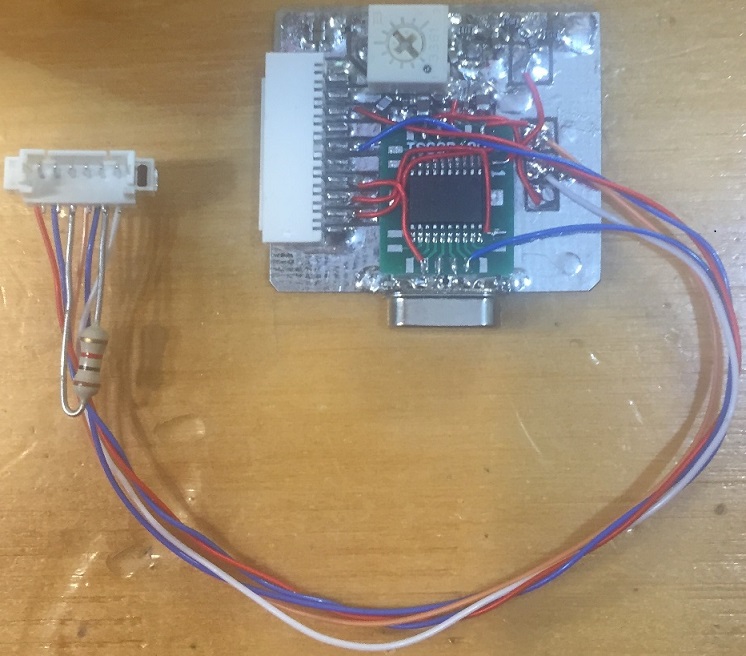
The object code for the Tone Unit is available on my github repo. The "SiLabs Programming guide" describes
the hardware and steps needed to program the project MCU.
|


